Week 7: Computer Controlled Cutting
In this seventh week of Fab Academy, I need to understand 2D design development of a CNC production, design a furniture within constraints and use minimum wood, try to make my hands dirty with ShopBot In the group assignment we need to test runout, alignment, speeds, feeds, and toolpaths for the machine. Further learnings from this week are listed below:
- Make something BIG using limited wood
- Make mistakes and learn from mistakes and also document the same so that I could save other's time
- Include design files and references
- Describe problems that I had faced, and how I fixed them
- Take photos of various steps and explain everything in layman's language
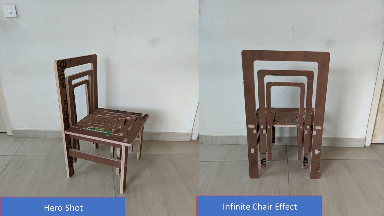
- Include hero shots of final assembled furniture
The following are the softwares that I have used for learning various operations:
- Autodesk Fusion 360 : 3D Modelling, Assembly
- Inkscape : CNC Machining
- Vcarve Pro : CAM Software
| |
|
|---|---|
| Wednesday | Prof. Neil's class on Computer Controlled Machining |
| Thursday | Learning more about the machine, test with CNC Design |
| Friday | Group Assignment, Safety Procedures, Trial Cut |
| Saturday | Documentation |
| Sunday | Documentation |
| Monday | Final Cut Begins, Cut interrupted |
| Tuesday | Final Cut & Assembly: Pending |
What is CNC Machining?
CNC machining is a manufacturing process in which pre-programmed computer software dictates the movement of factory tools and machinery. The process can be used to control a range of complex machinery, from grinders and lathes to mills and routers. According to the functions or types of machined parts, CNC machines can be classified into five types: CNC milling machines, CNC lathes, CNC drilling machines, CNC plasma cutters, and CNC grinders.
CNC Machine
CNC stands for Computer Numeric Control it is a process used in the manufacturing sector that involves the use of computers to control machine tools. Tools that can be controlled in this manner include lathes, mills, routers and grinders. The process involves creating a CAD(Computer Aided Design) file of the desired object. Then a specialized CAM (computer aided Manufacturing) software is required to convert the 3D CAD file into a set of codes which the machines can understand. CNC machining language, called G-code essentially controls all features like feed rate, coordination, location and speeds. With CNC machining, the computer can control exact positioning and velocity.
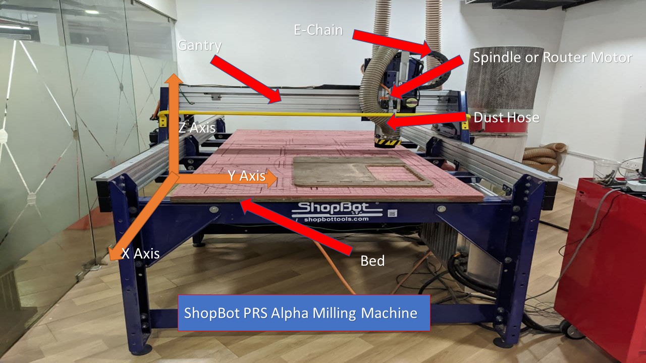
Shopbot PRS Alpha CNC Milling machine
A Shopbot is a computer-controlled cutting machine. A power tool router is affixed to the machine that directs its X and Y coordinates as it's cutting. CNC routers can be used to cut wood, foam, and plastics, but most hobbyists use it for carving wood. Founded in 1996 in Durham, North Carolina, ShopBot Tools, Inc., designs, manufactures and distributes CNC (Computer Numerically Controlled) routers for milling, drilling, and cutting of wood, plastic, metals and other materials -- powerfully, precisely, and affordably. The machine in our lab can cut 4x8 feet stock with 3 axis movement. It is a 3 axis machine the Z axis is perpendicular to the bed. The X and Y axisis are the length and the breadth of the machine respectively.To have a riggid supporting layer on the bottom of the workpiece we will place an additional piece of plywood above the bed called sacrificing layer .The sacrificing layer also protect the millig bit from damage by avoiding unwanted intereference with the metal body. ShopBot PRS Alpha have a speeds of 1800 inches per minute and cutting speed up to 600 inches / minute. It is easy to configure and easy to learn and also to use the Shobot PRS Alpha CNC Machine. The main parts of the ShopBot is shown below:
| XY Move Speed | ariable, max. 15.24m/min.ariable, max. 15.24m/min. |
| Z Move Speed | Variable, max. 9.14m/min. |
| Step Resolution | 0.0127mm |
| Linear Cutting Force | ≈150# at 60”/min |
| Positional Repeatability | +/- 0.002” (0.051mm) |
| X, Y, and Z Axis Drive System | Rack and Pinion |
ShopBoat has a powerful vacuum cleaner to suck all dust that comes when we cut something. A "Power On/Off" knob is also given. There is a wrench given in order to change the bit from the spindle.
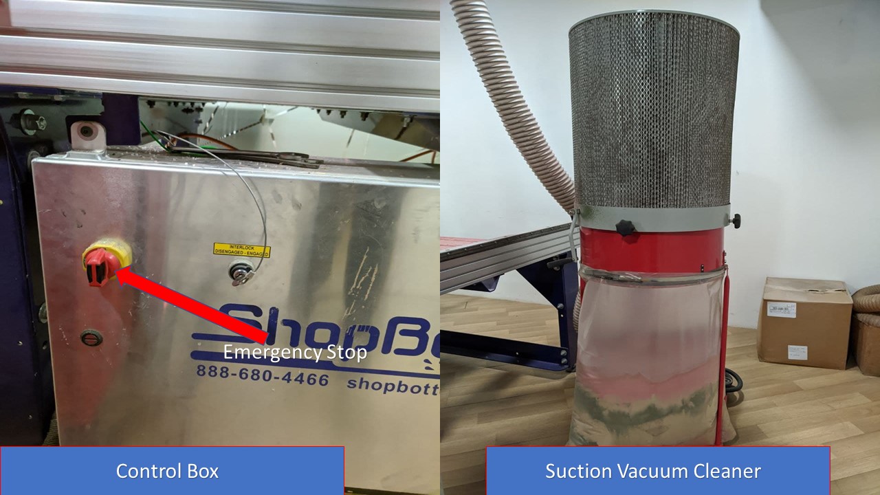
The power cables are always turned on before the cutting operation (that's obvious). ESTOP switch is Emergency STOP switches are used for stopping the work during emergencies there are two emergency stop switches will be there, One is ESTOP box which contains two additional switches one for Starting the spindle and the other for Reset. Ensure these ESTOP switches are in the OFF position position by rotating the RED STOP button on the DONGLE COUNTER CLOCKWISE
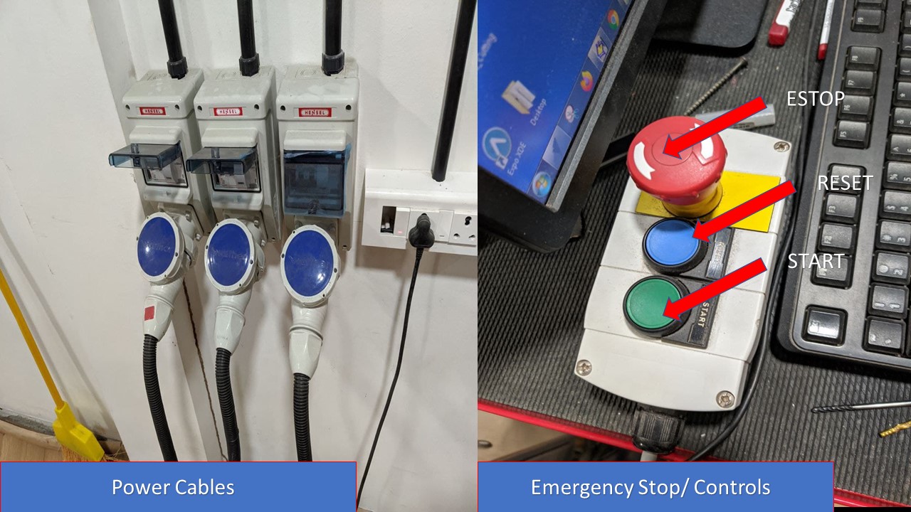
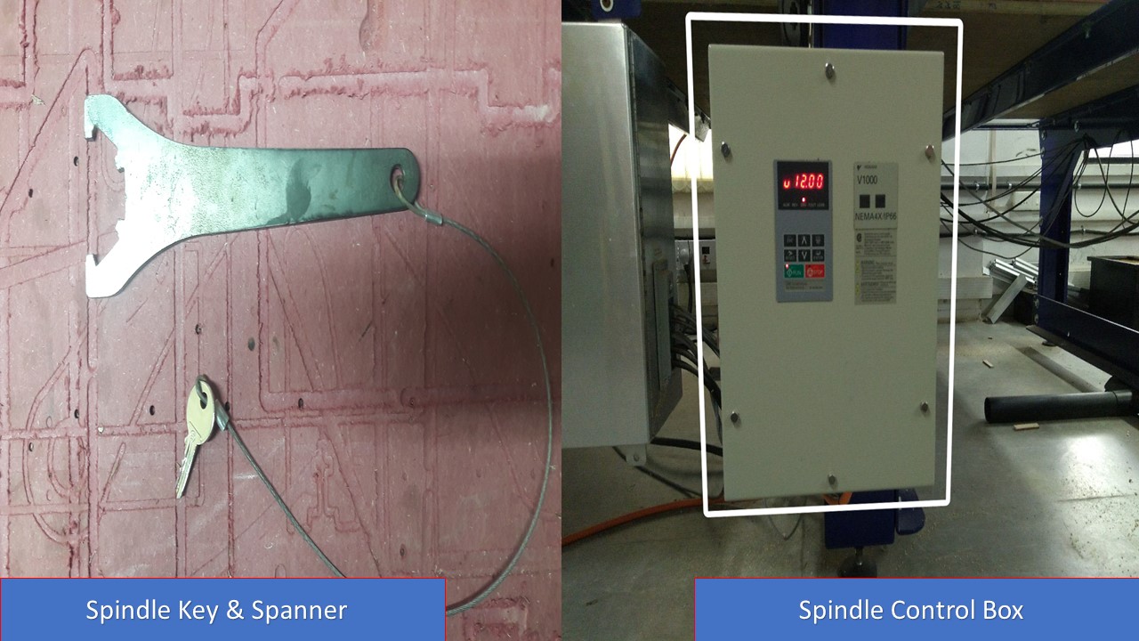
There is also a spindle control box and a spindle key and spanner to set the Z height. The key also acts like a safety feature to prevent damage to human and equipment.
It is important to consider safety while working with Shopbot. There are chances of debris falling in eyes, loud noise and protection for hands should also be considered.

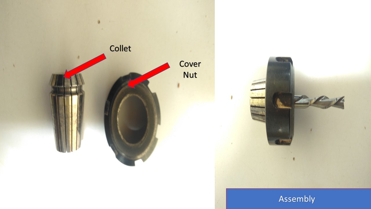
A collet is a subtype of chuck that forms a collar around an object to be held and exerts a strong clamping force on the object when it is tightened. It may be used to hold a workpiece or a tool. We are using ER25 collets, ER collets are slotted (alternately) from both ends and therefore compress onto the cutter along the whole length of the collet when tightened. This not only provides a better grip on the cutter shank but also allows some variation (typically 1mm) in shank sizes that may be used in a single collet. The smaller size collets are best used to hold cutters no more than 0.5mm below the nominal size. Collets are inserted into the covernut.
Drill Bits vs End Mills
CNC machining is a subtractive process that uses rotational cutting tools called “end mills” to remove material. An end mill, while similar in appearance to a drill bit, is far more versatile. However, in practice the terms “bit” and “end mill” are often used interchangeably
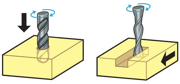
Flat/ball end
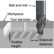
Flat end leaves flat surface profile on the stock and are good for removing large volume of material, but steps are formed when used for making curved surfaces. Ball end leaves curved surfaces and forms smooth curved finish while cutting cavities. They are used for finishing cuts.
Bit Specifications
- Bit material: Router bits used in Shopbot are made from a variety of materials such as solid carbide, carbide-tipped steel, and high-speed steel.
- Flute type : There are four basic flute types: Straight, spiral up-cut, spiral down-cut, and compression
- Chip load :- This is the amount of material that is removed in each chip. The value is approximately = feed rate (inches per minute) / (RPM x number of flutes)
- Cut depth :- This is the measure of how deep the end mill should go in each step while milling. Ideally cut depths should be less than 1/3rd of the length of the tool. They are mentioned in the product manual of the tool bits.
- Step over :- In a pocket cut the machine will traverse the entire area of the cut. It does that with a series of paths that cover the entire length and width of the cut. While doing this the step over determines how much the adjacent paths overlap each other. Usually we use it at 50%, ie the adjacent end mill cuts will overlap 50%, which gives a better finish.
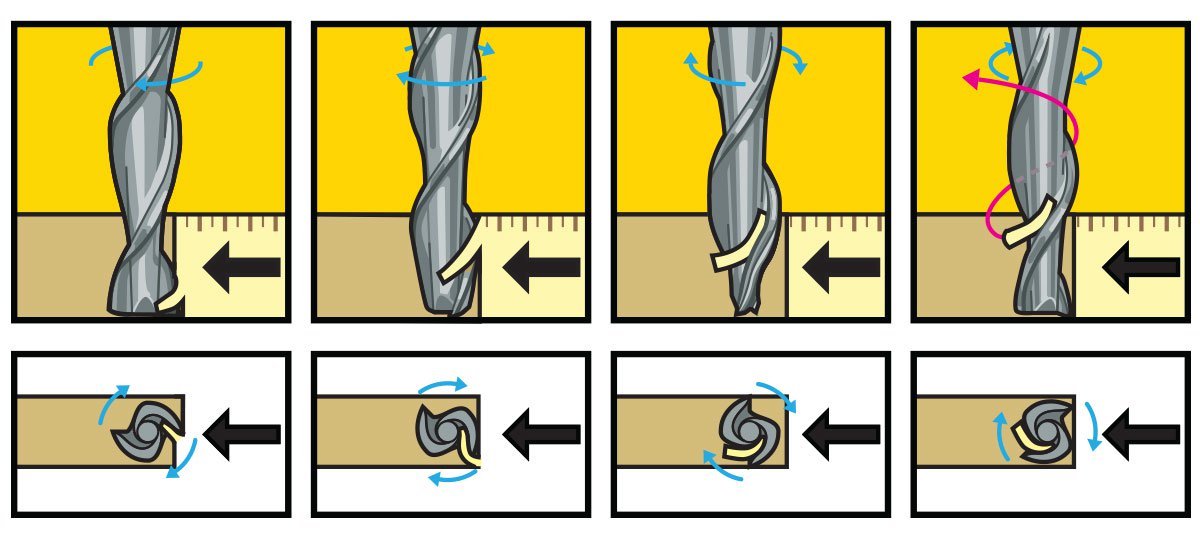
UPCUT & DOWNCUT
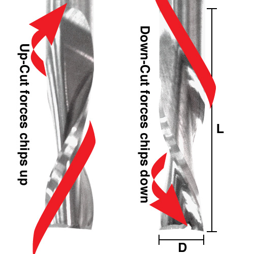
In an Upcut type end mill the teeth on the flute will point upwards. This means that the end mill is cutting and drawing out the wood through the flute. This is good for cutting deep into the stock. But this leaves a bad surface finish on the top of the surface. A downcut type end mill has teeths that point downward on the flute. This means that the end mill will cut and try to push the material into the stock. This will give good surface finish on the top, but it is not very efficient at removing material.
Flutes and Chipload
Flutes are the helical grooves that wrap around the sides of the end mill. Each flute has a single tooth with a sharp cutting edge (although there can be more than one) that runs along the edge of the flute. As the tooth cuts into the wood, each flute whisks away a small section or “chip”. The fewer the flutes, the more material that is ejected with each tool rotation. The overall cutting depth should never exceed the length of the flutes on an end mill. If cutting deeper than the length of the flutes, the tops of the flutes will be blocked and chips won’t clear, building up heat and reducing tool life
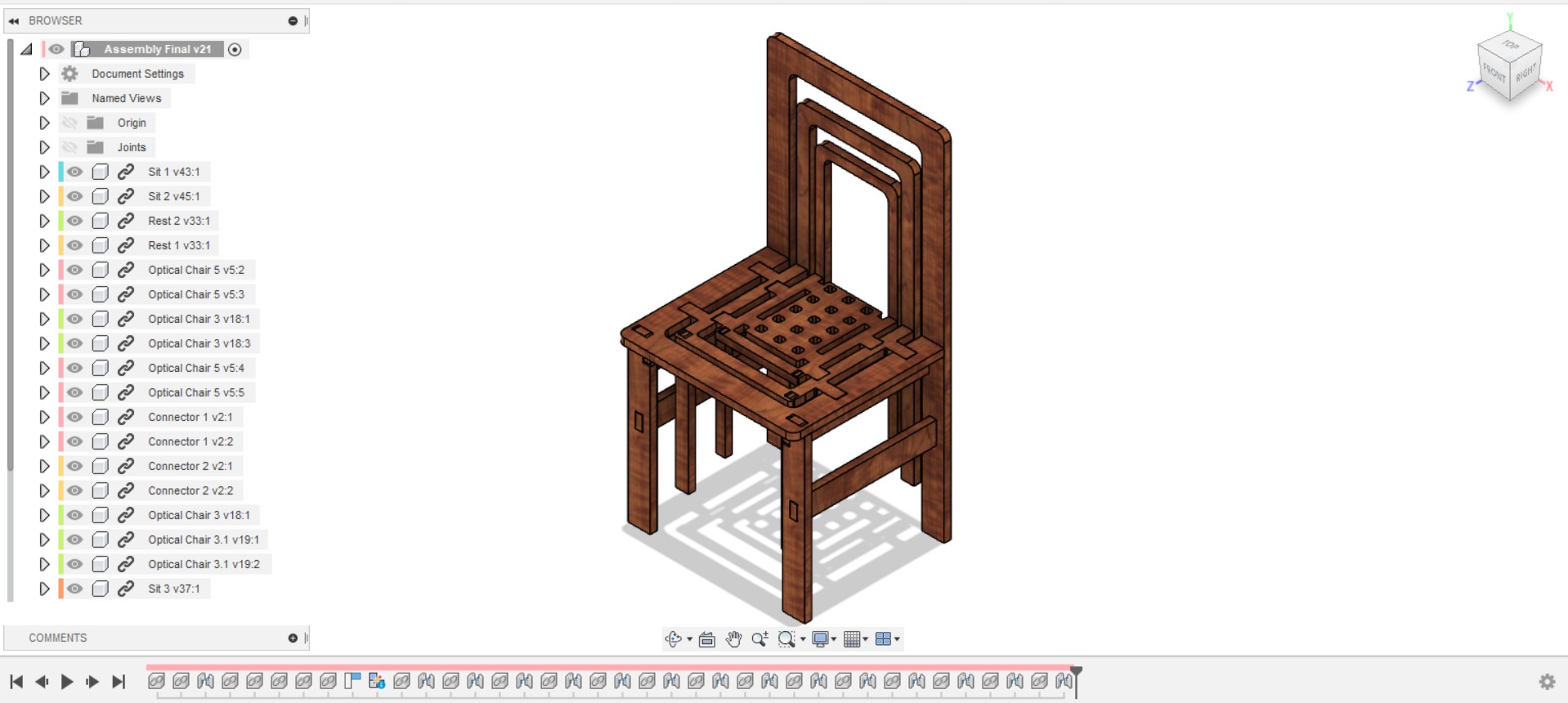
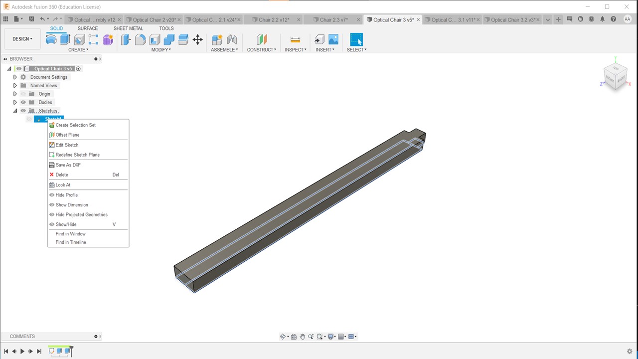
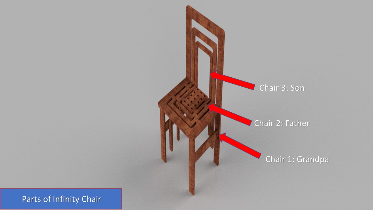
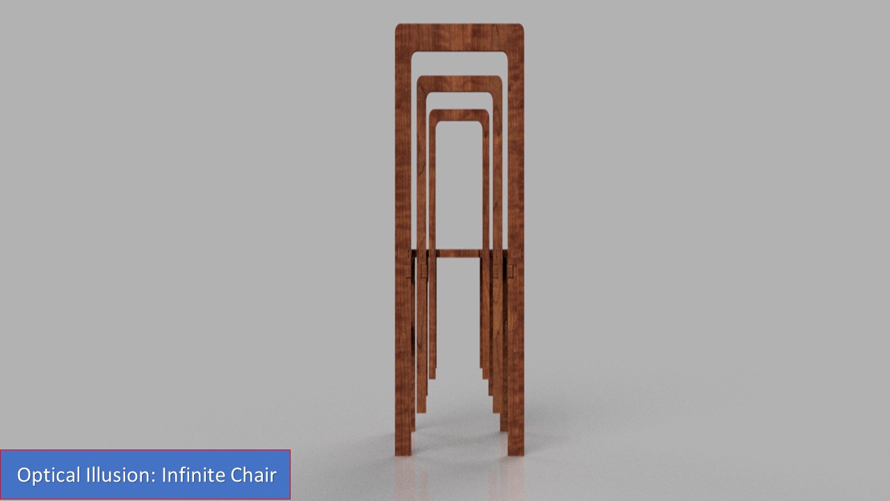
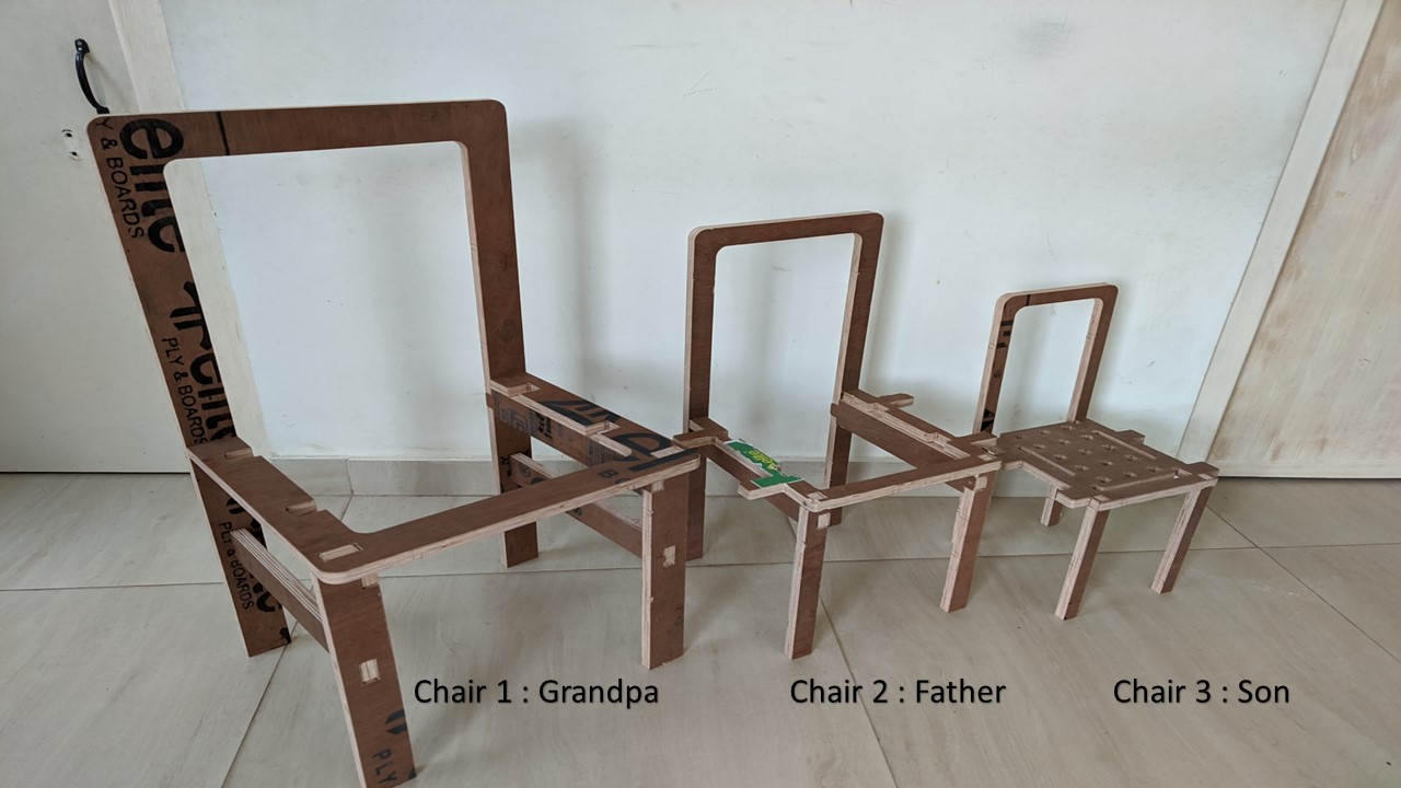
For this weeks Individual assignment, I first thought of making a rocking chair but I changed the idea since I wanted to do something different. For that a Youtube video inspired me to make a chair that looks like infinite chairs from back side view and is capable of incorporating 3 chairs in a single chair. It took a lot of time to ideate about the project as I couldn't make a single chair and scale it down. So I had to individually design each of smaller chairs inorder for it to fit to the bigger one. Another interesting fact is that the infinite chair effect is caused due to optical illusion, so yeah this can fool you (kidding). For fun, I called these chairs as grandpa, father and son chair all in one set. My intial design had used pockets to fit the inner chair to outer chair but I found that there is a high risk of failure if I chose that design. So with the help from my instructor Mr. Jogin, I redesigned my chair providing more cross structural members to provide more strength that it won't break. The modified design is shown below:
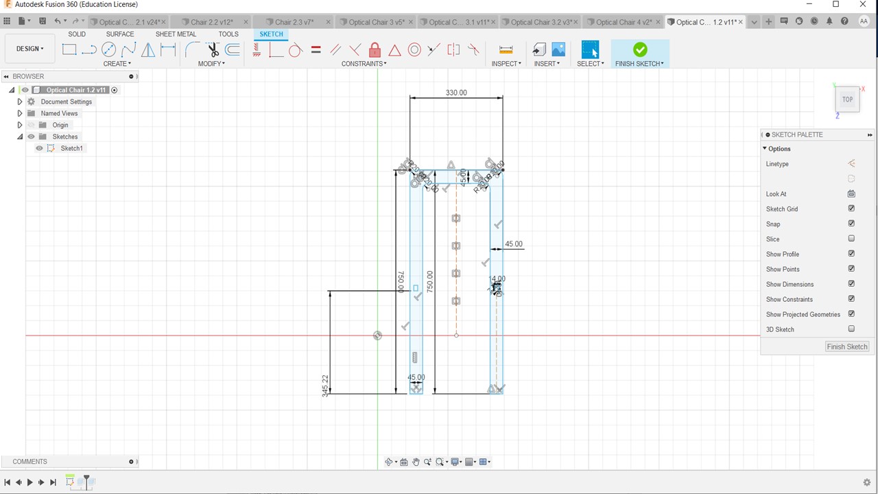
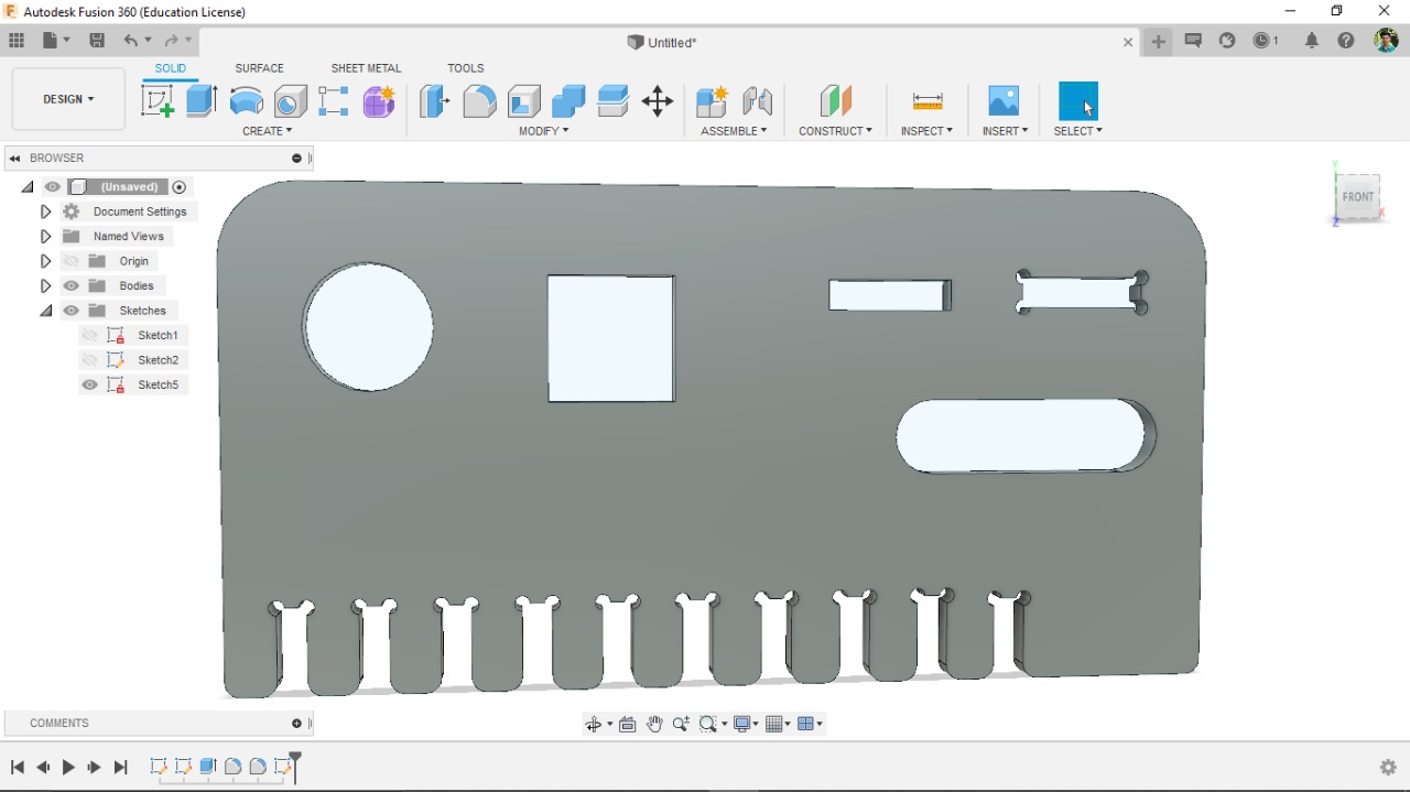
First, I started working on the second chair as it contains both the slot and the extrusion. With the help of my instructor Mr. Rahul, I had to fix the depth of slot in such a way that the wood won't shear when weight is applied. So I had used the depth of slot as 10mm while keeping the extrusion as 8.4mm (including kerf). The process is repeated for smaller and bigger components.
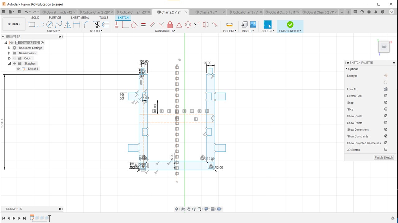
The same procedure was followed for the other parts keeping in mind the kerf values.
The next step was to test cut the model in Laser Cutter and ensure the practicality of the model. For that I had exported the drawings as DXF and imported the drawings to Inkscape. Then I had to scale the model to fit the bed size and tried to cut it using the required software.
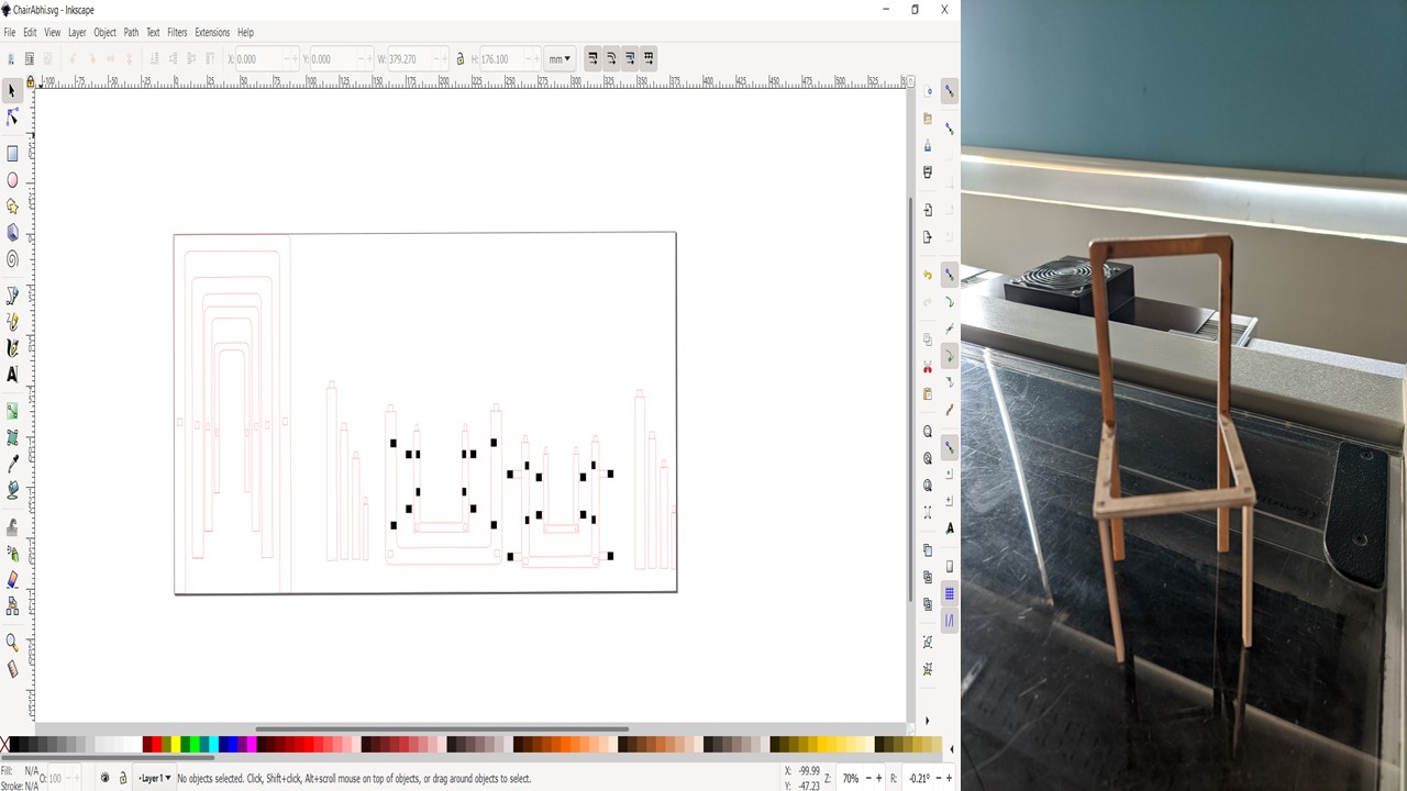
From this experiment, I found that I needed to provide more support to the legs and need to increase the width to provide enough strength for chair to prevent failure duing loading. The following images depict the rendered image of the infinity chair. I also had reduced the number of chairs from 4 to 3 as I was told the smallest chair would easily break since the thickness of the wood is too low.
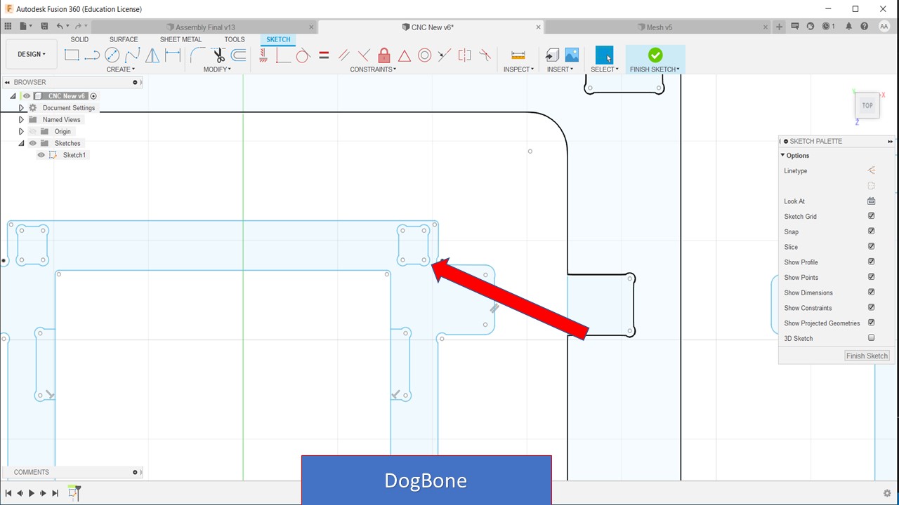
Before converting to DXF file I need to create a dogbone for the press fit and I had used a AddIn in Fusion 360 which helps to add dogbone to the sketch with ease. The AddIn can be accessed from here and you need to extract and paste the folder in the AddIn folder directory.
The next step is to import the model as DXF for the VCarve Pro software. So ensure that your sketches are in perfect dimensions and there are no mistakes before you go to next step.
The ShopBot is like any other CNC machine which we have used previously. It runs on a series of commands which are called G-codes. These codes are like instructions executed line by line, they tell the machine where to move and what to cut. There is a whole host of processes involved in computer controlled cutting, and it all starts with a CAD design. The process of preparing for the cut is similar to other CNC machines, first you need to design what you are going to cut using a designing software like Fusion 360. You can design in your favorite design tool and export as a .DXF file which can be used by Vcarve. I had used Fusion 360 and exported the sketch as DXF. Once exported to CAM software the VCarve converts the drawing to GCode which provides command to the machine.
Setting up ShopBot
Here are the steps involved in cutting your favorite model. Before working with this machine you must understand that safety is your atmost priority. Never keep your hand in the bed while machine is working and never leave your work as the dust particles can cause fire. Always wear protective gear. After the safety precautions are taken then you can move to setting up of the machine for the cut.
Before you load the material you need to change the cutting bit to the required one. The steps involved are as follows:
- First, turn on the CNC Machine
- Warm up the machine
- Make sure the router bit is safely above the table
- Move the router to the table using the toggles in yellow control panel
- Unlock the Interlock Wrench and grab its counterpart
- Loosen the vacuum hose brush
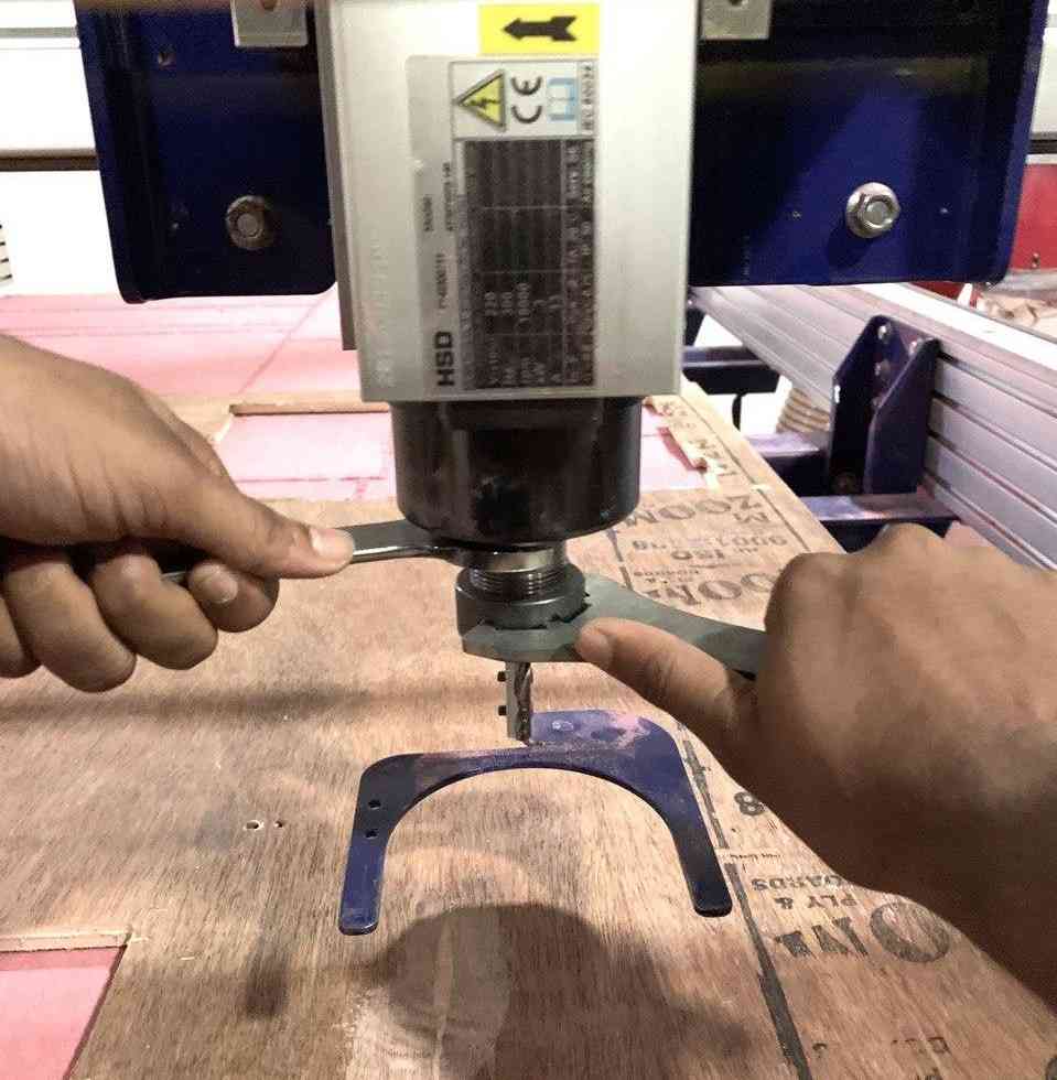
- Loosen the collet using the two wrenches as shown
- Change bit or hand tighten a new collet with a bit needing a different shaft size
- Tighten collet and retighten the vacuum hose brush
- Finally, choose the speed for the router based on the bit
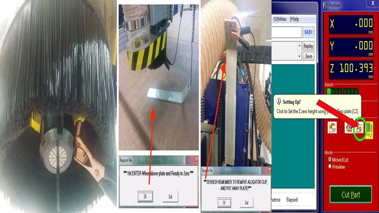
Setting up the Z-Zero Height
- First pull the Zeroing plate and alligator clips off the router
- Attach the Alligator Clip to the Zeroing Screw on the CNC Router
- Place the Zeroing plate directly above the router
- Call C2 on control panel of the ShopBot software, and it asks you to check whether the aligator clip and plate are in correct position
- Watch the Zeroing process to ensure the bit will hit the plate
- Another pop-up will appear on the screen asking you to return the Alligator Clip and Plate.
- The router should stay at a safe height above the table after being zeroed, however, if need be, raise the router safely above the table
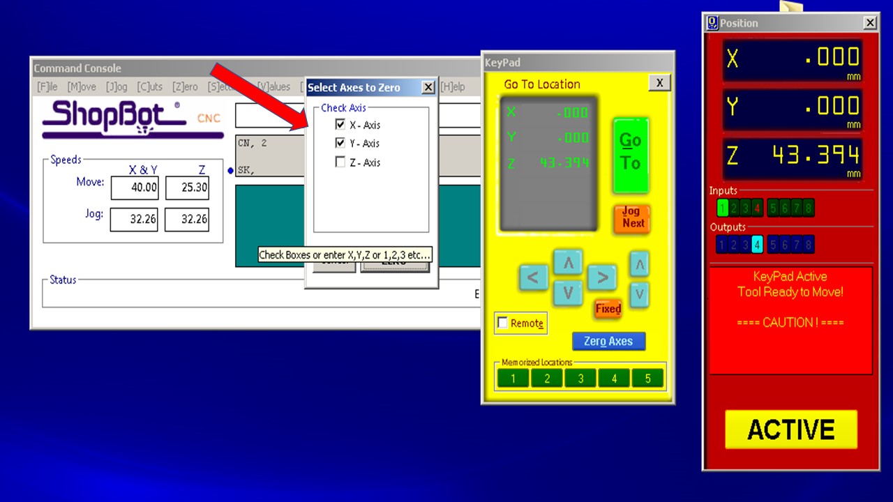
Setting up X-Y Axis
- Use keypad to manually set X and Y using 3 buttons
- Ensure that the spindle is in the top right corner of the bed and after clicking the zero axis button in the software, the X and Y axis values are zeroed
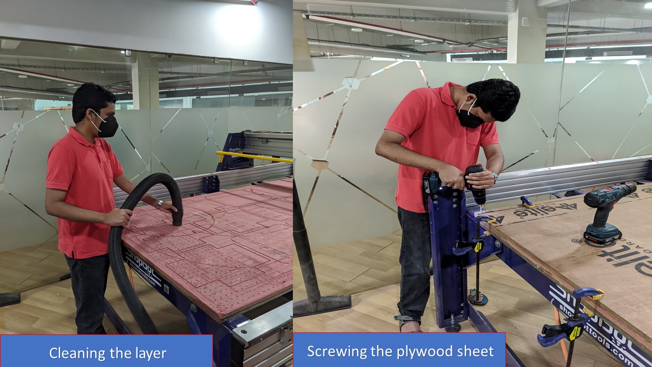
Preparing Material for Cut
The first step is to clean the sacrificial layer and mount a new plywood to the layer. Here I had used 18mm plywood. Now, since you have prepared the workpiece now we need to cut it.
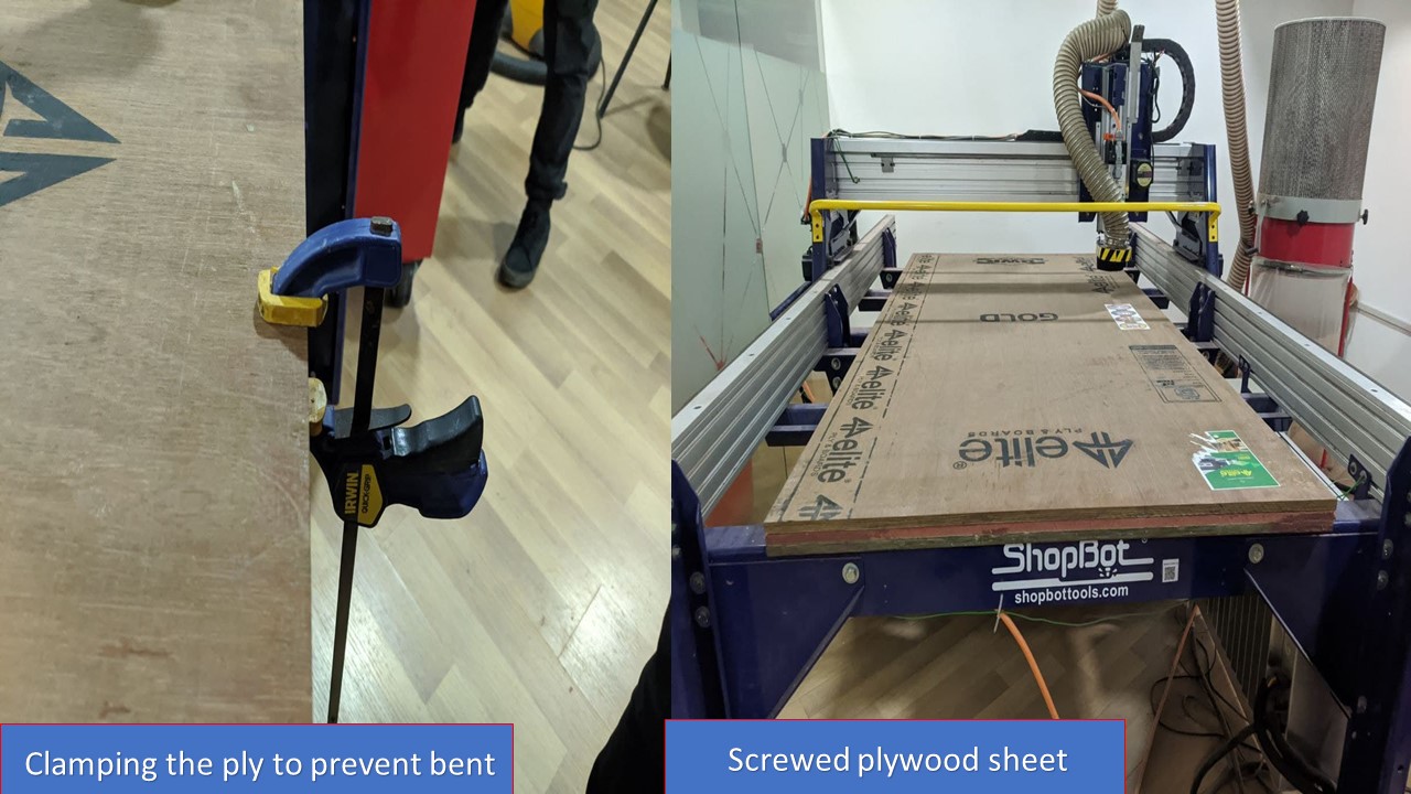
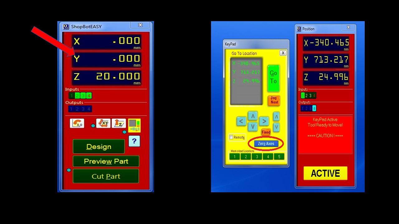
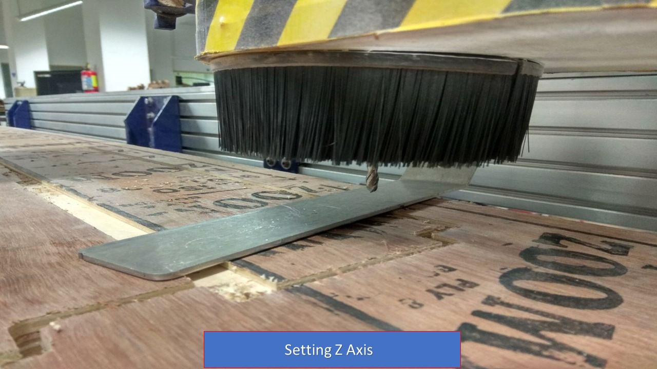
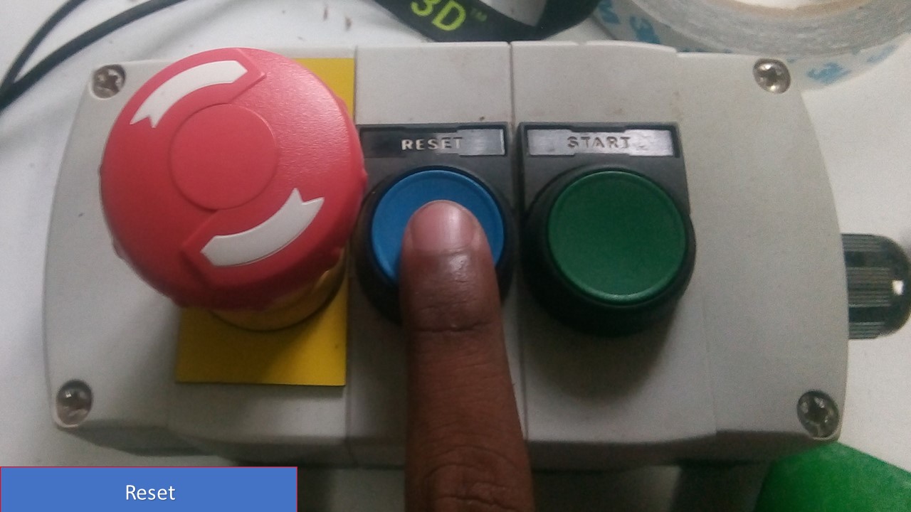
The next you need to open the ShopBot CNC controller, and you need to reset the axes from the previous work. For that twist the controller in the control box and push Reset button. Now position the control box and set X,Y and Z axes. Then Click on zero axis and Tick all the boxes. We can adjust the X and Y axis by usig the Arrows in the software, after that we need to set the Z axis.For setting the Z-axis we have a plate which is electrically connected to the machine.Place the plate on the surface and the machined is moved on z axis to touch the plate.This completes the circuit and z axis is marked.

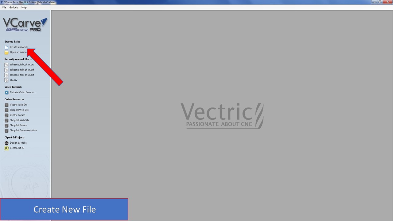
The next step is to open VCarve Pro and create a New File and add the dimensions of the 18mm board that you are going to take. I chose this method rather than directly importing the file's dimension inorder to be on the safer side.
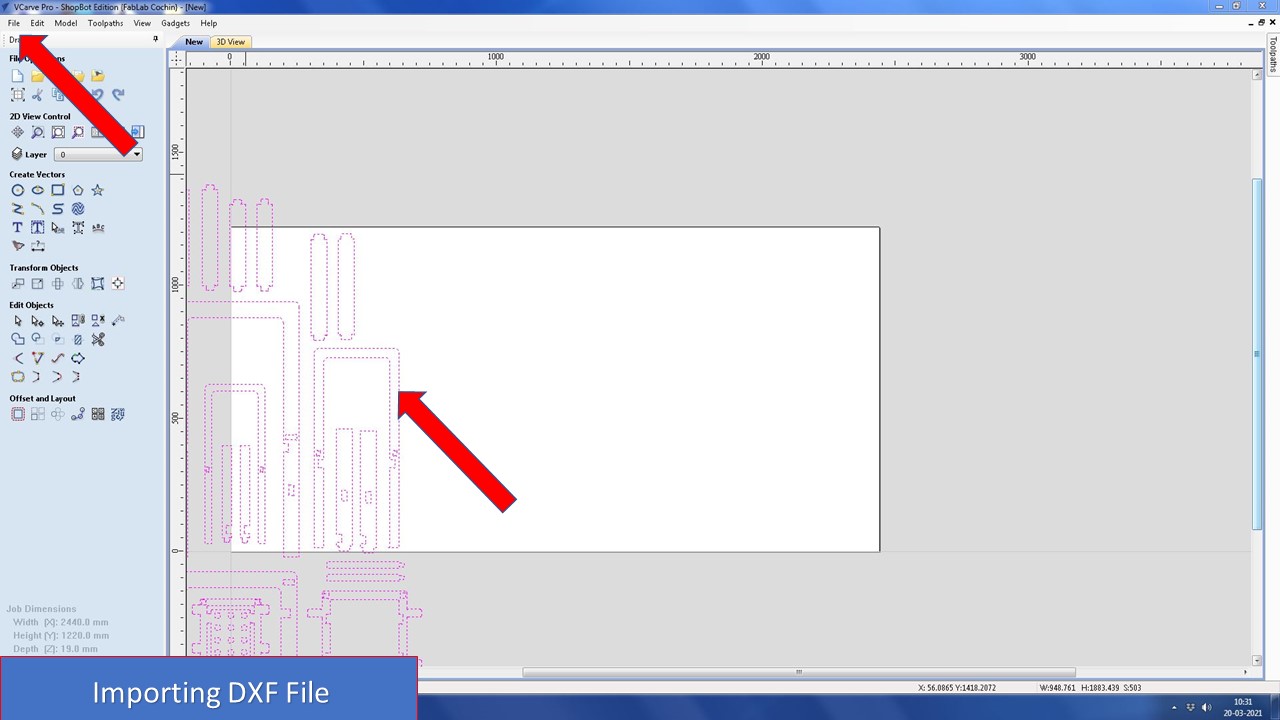
The next step is to import the required DXF file by going into File -> Import and you need can see that the sketches get imported to the dimensions of the sheet.
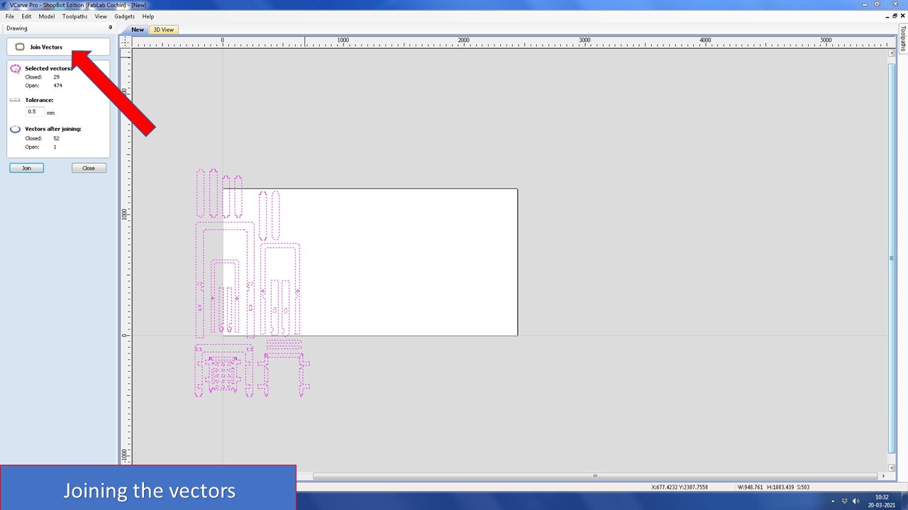
Now you need to select join vector command to join all the open geometries and you can also provide a tolerance for the same (I gave as 0.5mm as no geometry is below that value in my sketch)
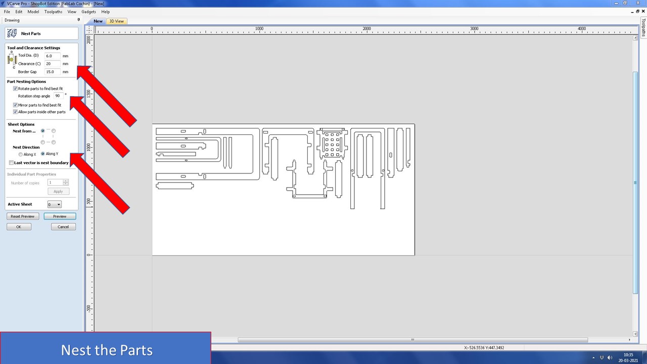
The next step is to nest all parts (arrange) to fit it optimally without wasting material. For that you need to define tool diameter, clearance & border gap. I rotated the parts 90 degree to find the best fit keeping the next direction along Y axis. You can try different combinations to get the best fit
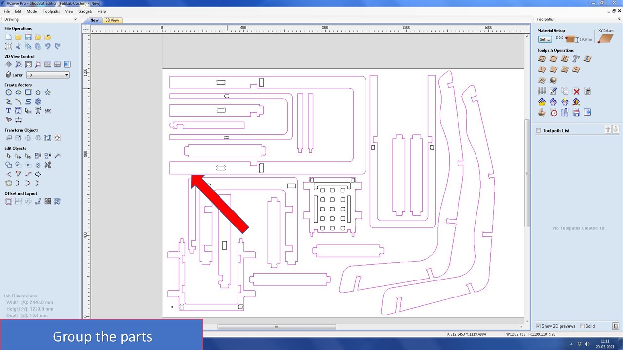
If you want to add more geometries to fill the gaps you are free to do so. In my sheet, I had imported my friend's parts also so that he won't need to cut it in another fresh sheet. Now the next step is to group all the inner cuts and outer cuts. You can do so by selecting the respective geomtries and grouping it by right click.
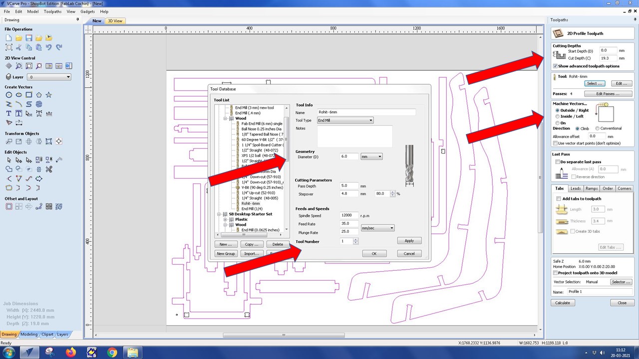
In this step you need to select the cutting tool, here I had selected 6mm dia with step over of 4.8mm, pass depth of 5mm. You also need to provide the starting depth and the cut depth. I had provided cut depth as 19.3 since in some areas the ply is more than 19mm. Since it;s outside cut, I selected outside and next you need to add tabs and ramps.
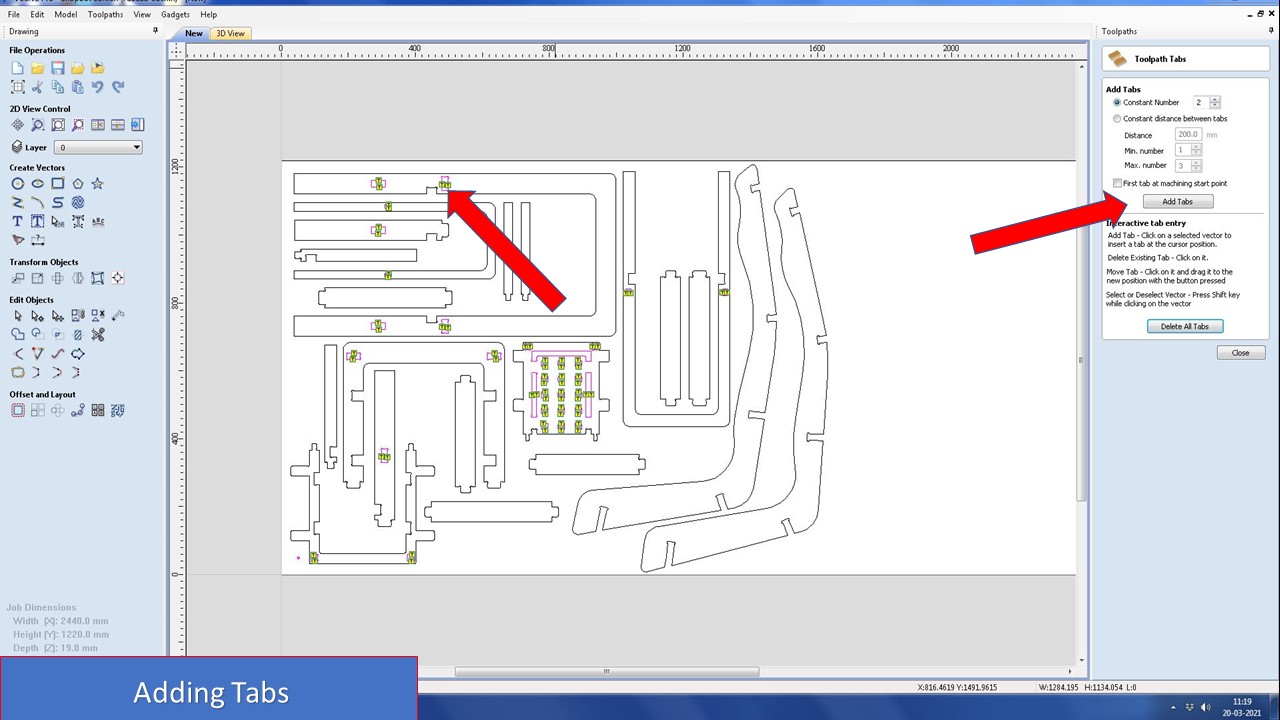
In this step you need to add, the tabs. For that you can choose automatic tab selection but I chose it to do manually since it would be easier to remove it after the cut.
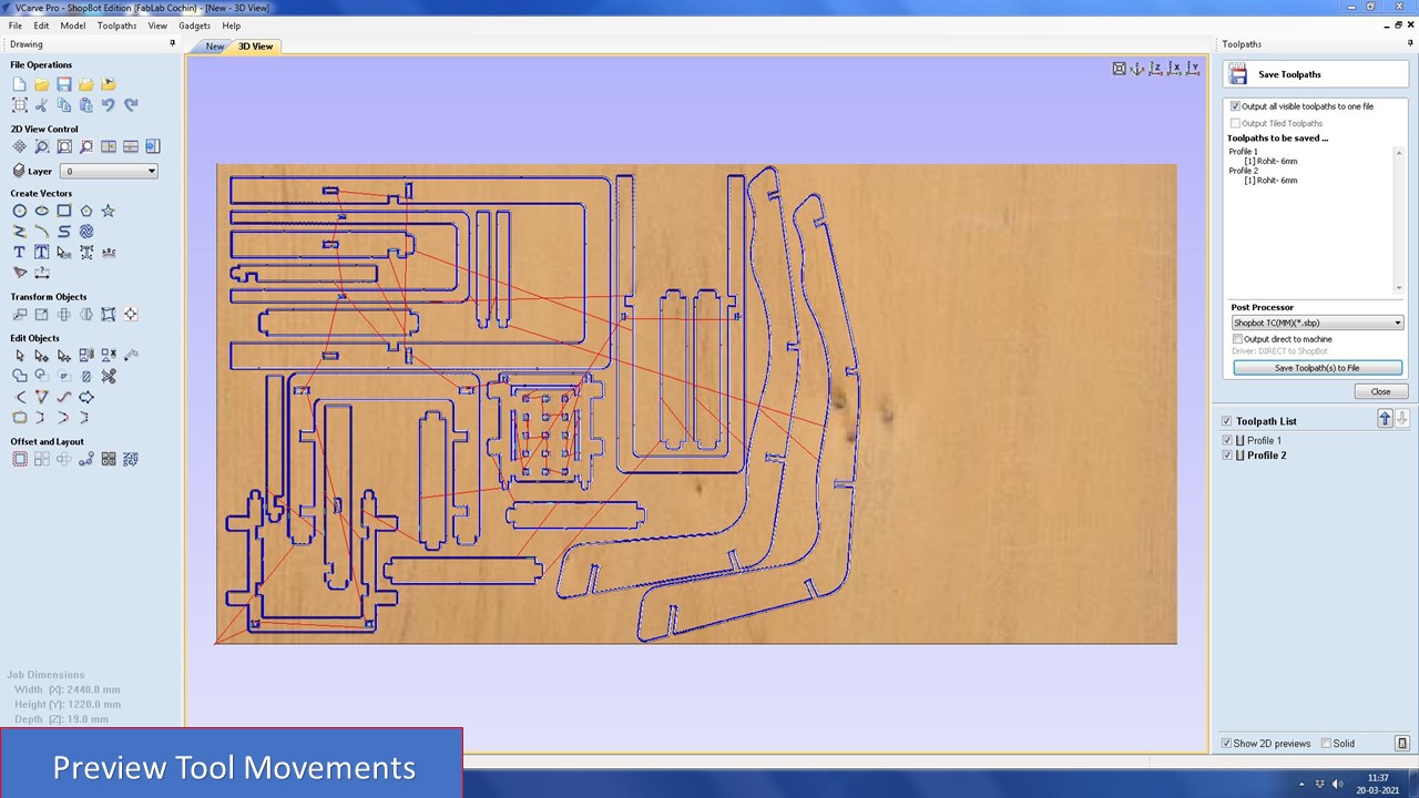
Similary repeat the above steps for outer/inner geometries. Once you had done that select the preview option to check how the tool cuts the ply and save the file as .crv.
Cutting
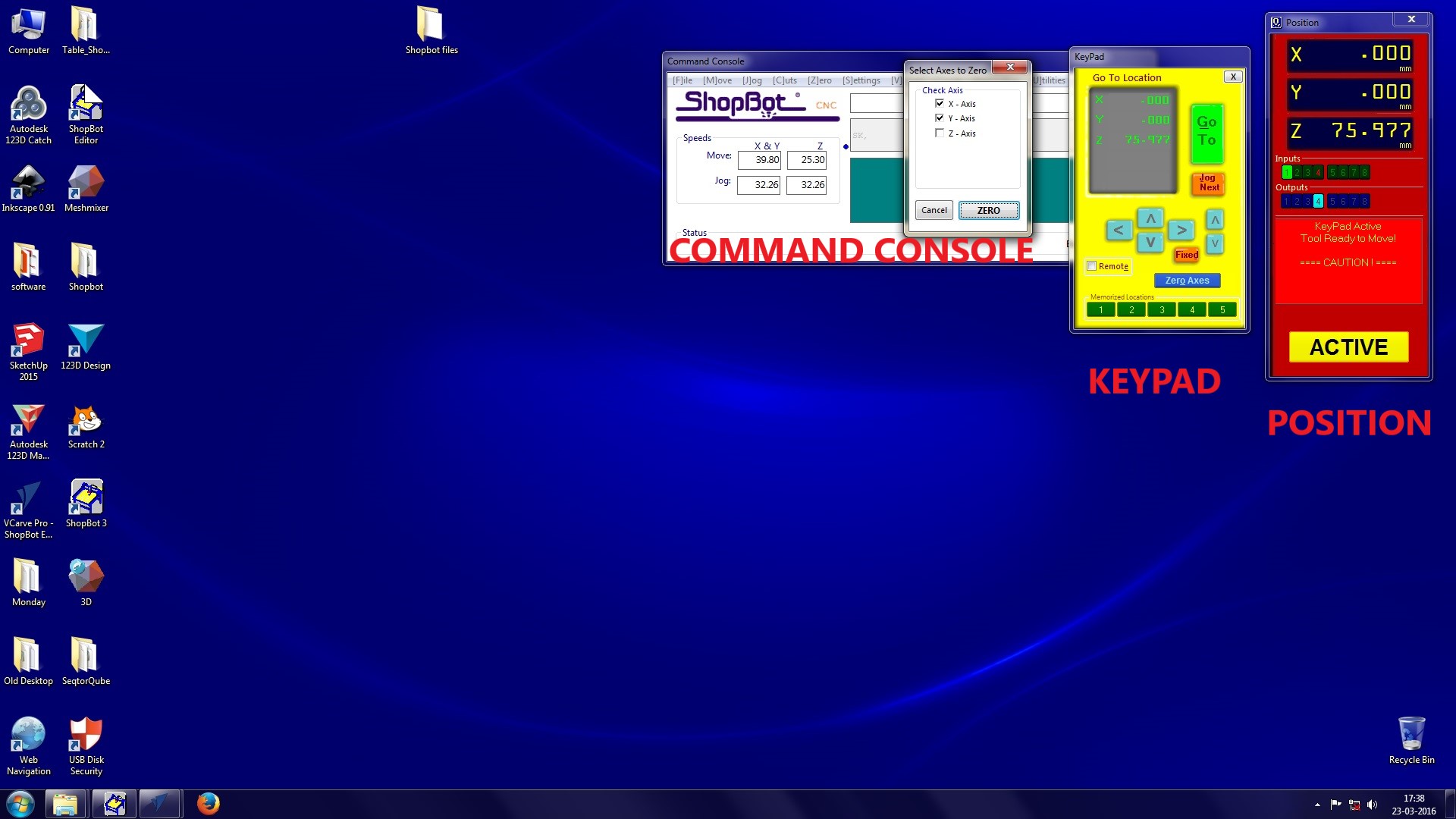
Next you have to open the file in the shopbot application. The software has a simulated DRO(Digital read out) and it has 3 main parts
- A position feedback main window .It shows the status of all the functional parats of the machine.
- A simulated keypad for manual jogging and setting origins
- An Integrated command console.
So we have prepared the work piece. Now we need to cut it. for that open CNC controller.
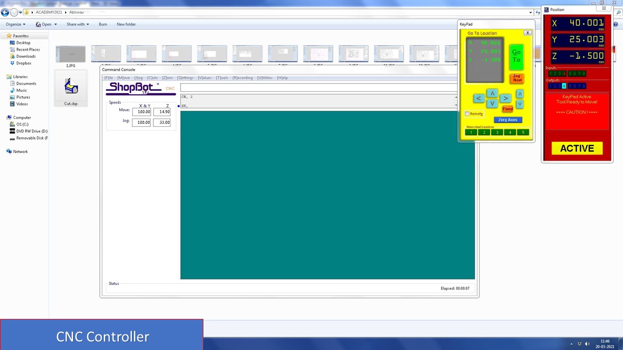
Now you need to reset the axes from the previous work. For that twist the controller in the control box and push Reset button.
Now open position control box and set X,Y and Z axes. Click on zero axis and tick all the boxes. Then you need to add the design file needed to be cut. For that click on "Cut Part". Open the first file and follow these steps.
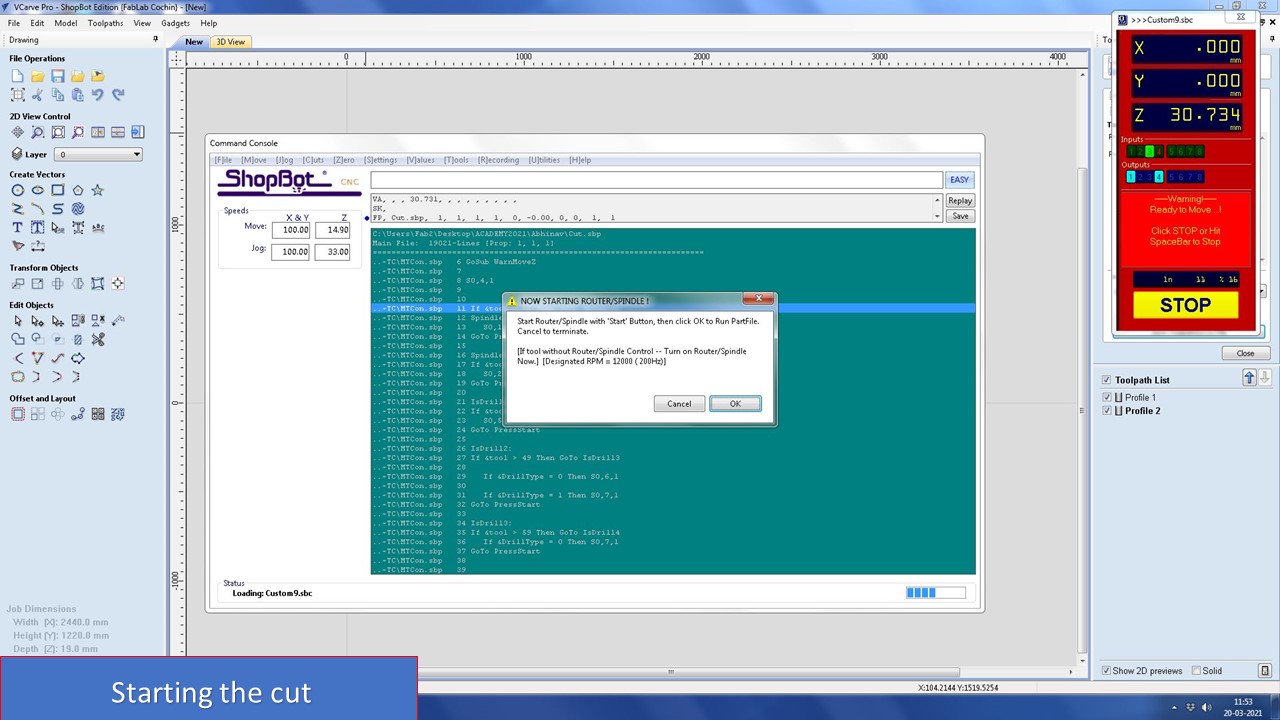
- Click start
- Click "start" button to start the spindle from control box and ensure that the spindle is ON.
- Click "ok" on the screen
- The process will start immediatly.
The cut went smoothly, but then there was a twist. Due to some unexpected error the machine stopped at 50% of cut and I along with my instructor Mr. Joel troubleshooted and since I had saved the origin point, I was able to resume the cut without fail. So ALWAYS NOTE THE ORIGIN COORDINATES. A timelapse of the cut is shown below:
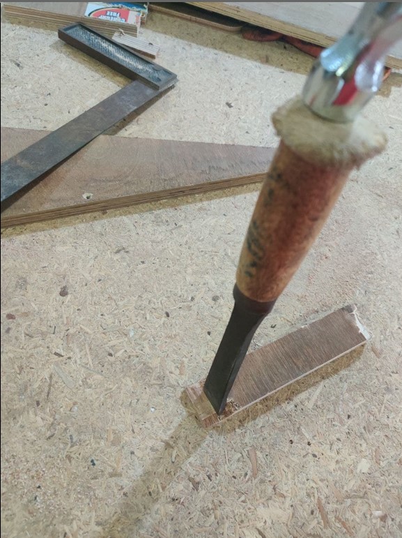
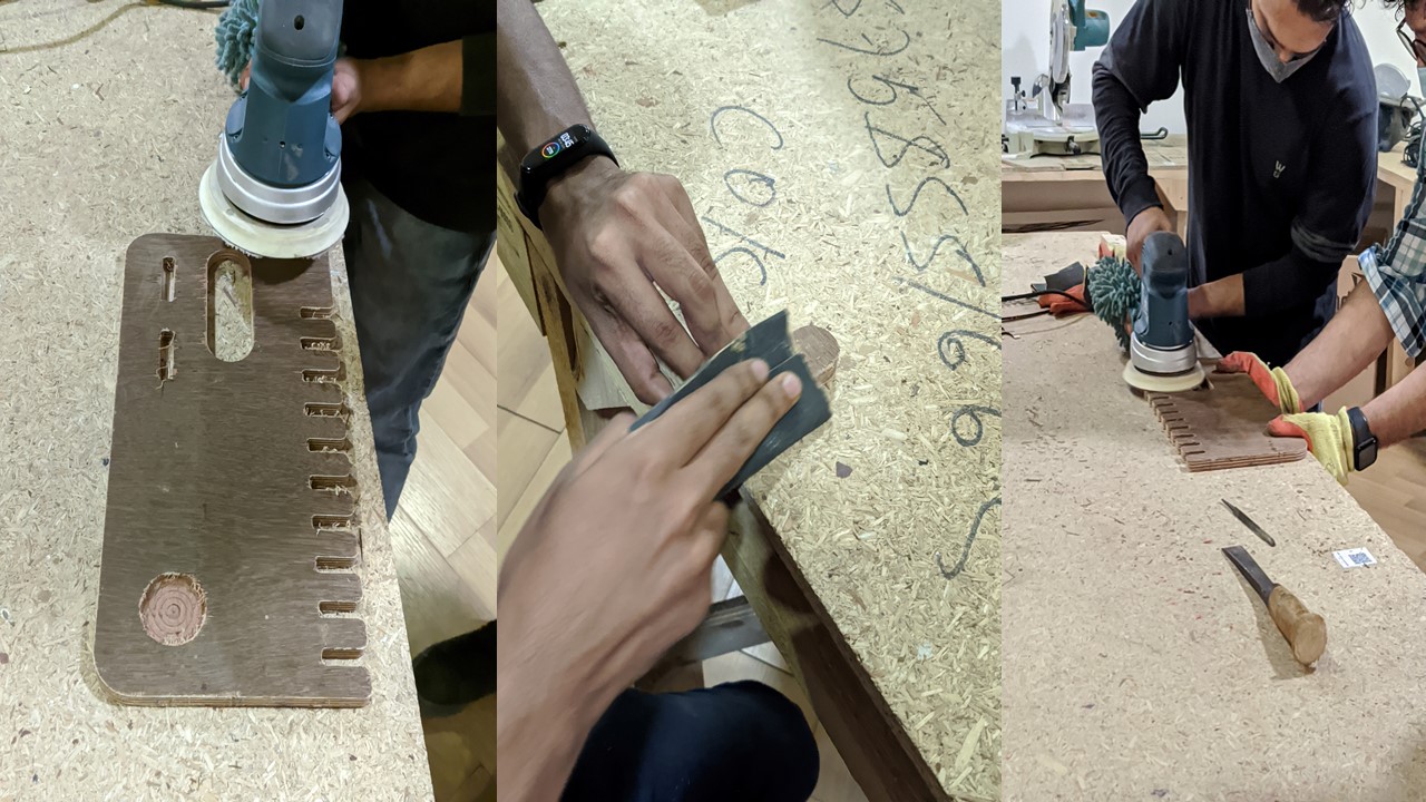
After the cut, had finished you need to remove the parts using a chisel and a hammer. i.e. you need to break the tabs and remove it
Hurray, my cut was completed successfully. Since my tolerances and clearances were great, it didn't take much effort to file and assemble the components (thanks to my friend Pallab). I had assembled the whole model within 2 hours and the results were amazing. The project was warmly welcomed by the instructors due to its uniqueness. I will add some pictures showing its beauty
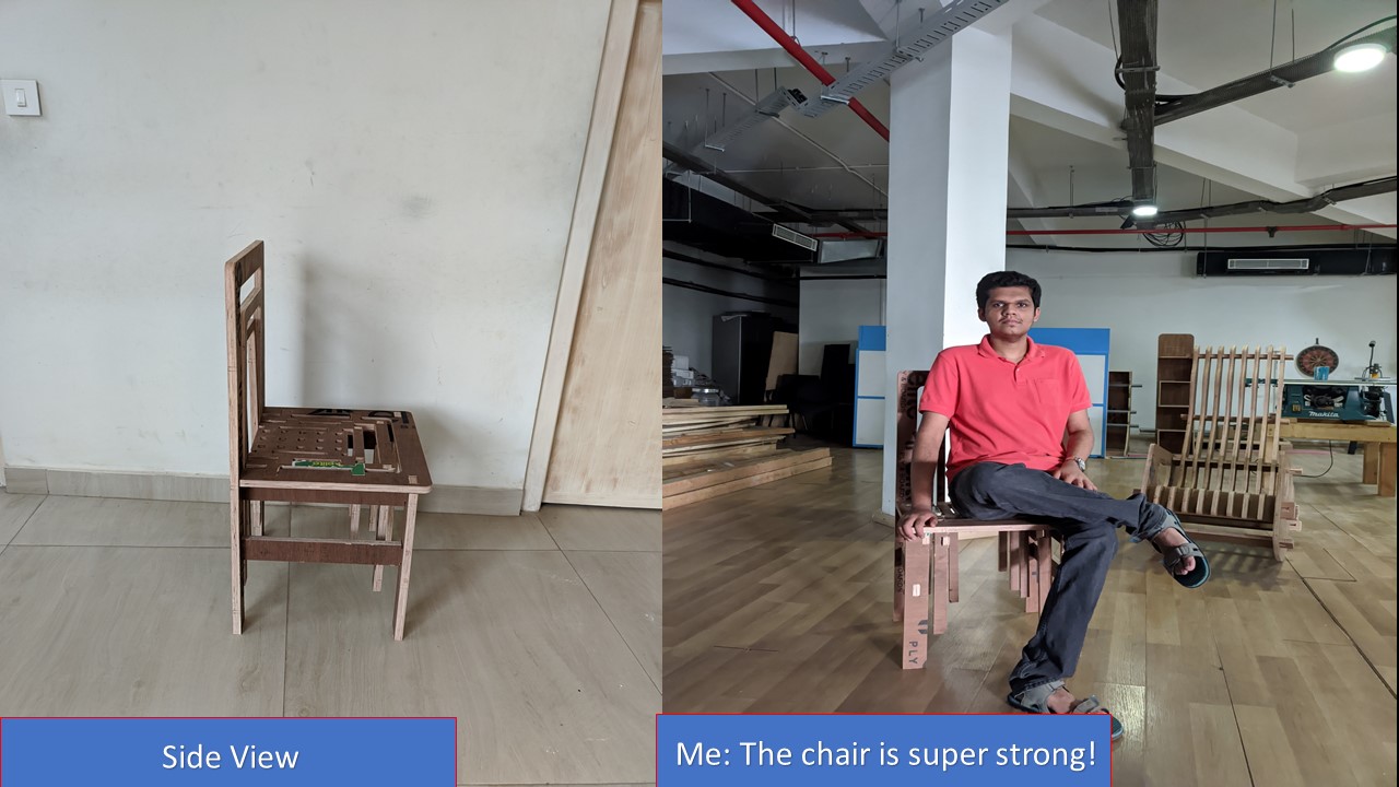
Even though I had to wait for my slot to cut the model, it felt good when it assembled perfectly. I tried to adapt the model based on other's feedback and the result was that the final assembly fits well and only took limited effort. I thank all my friends and instructors who helped me to make this into reality and if possible I will try to add a timelaps on assembly/disassembly of this piece of art!
This week We need a test runout, alignment, speeds, feeds, and toolpaths for our machine by part of our assignment. So for testing some parameters in shopbot, we have designed a structure in Fusion 360.
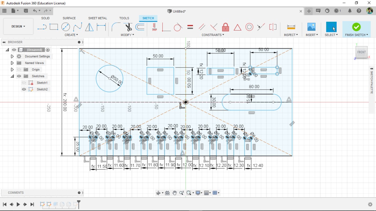
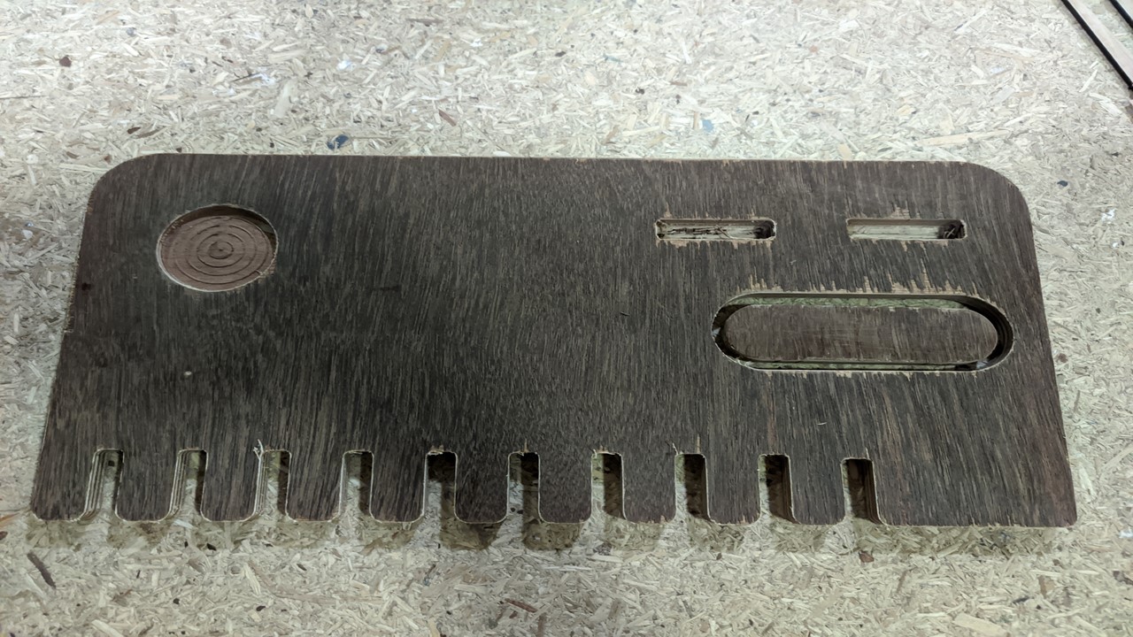
This was our group assignment to find the press fit dimension for the 12mm and 18 mm plywood .So we cut slots from 18.60 to 17.80 in steps of 0.1mm and for 12mm from 11.70 to 12.50 in steeps of 0.1 mm. We found out that the right press fits comes somewhere near 18.6 mm and 12.4 mm. The material thickness does vary a bit with temperature, moisture etc. To our surprise we found later that the 18mm ply actally had 19mm thickness in majority of the areas. So I think it's time to change the suppliers.
- Wear proper eye and body protection while working with ShopBot.
- Don't mess up units, if you design in mm, give same value in Vcarve.
- Select proper feed rates and cutting speed for each bit.They will be specified in the manual for the end mill, you can experiment with values you get from the manual.
- Ensure the inputs are being detected, before giving the option for Zero setting. Touch the Zero plate on the bit and check your control panel if input a lights up. Only then should you proceed.
- Always start from the machine home position when you want to set your X and Y origin, and note down the values in case of emergency stops.
- Do not press OK to at the last menu and start cutting without turning ON the spindle.
- Don't leave tools on the bed of the machine when it is running. The machine's movement is unpredictable
- When changing the bit, don't put too much force in the XY direction as it will change the current position of the spindle and ruin the rest of the cut.
- Don't press any keys on the computer when the machine is running, it will pause.
- For any emergency you hit the stop button, then the entire program is gone, you will have to start once again, Hence it is advised to note down the origin position with respect to the home position
- Always recheck the plywood dimensions using vernier before cut, I had used 18mm ply but the actual thickness was around 19mm so recheck several times before cut and change the dimension accordingly
- Give fillets for easy pressfit and give clearances otherwise you may have to spend lot of time and effort in filing